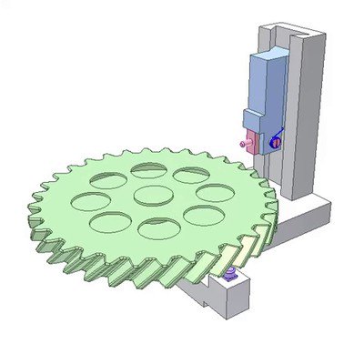
It is a structural embodiment of “Parallelogram and internal gear mechanisms 1a”
h – p = 2e
h: diameter of two holes on the plate.
p: diameter of two pins on output green crank.
Lines connecting the hole centers and the pin centers D1C1 and D2C2 (playing role of bars of the parallelogram mechanisms) must be parallel to pink input crank.
Z1: tooth number of external gear (= 30).
Z2: tooth number of internal gear (= 60).
n1: pink input crank velocity
n3: green output crank velocity
Transmission ratio i = n1/n3 = Z1/(Z2-Z1) = 30/(60-30) = 1
Pink and green cranks (coaxial in opposite sides) rotate in opposite directions with the same velocity.
 mechanical mechanisms
 Spatial Ratchet Mechanism
 Screw Gear Overrunning Clutch