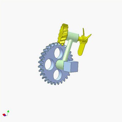
Output: blue gear with a male cone. The red arrow represents load (to be raised or descended) applied to the gear.
The yellow ratchet wheel with a female cone rotates idly. It is connected to the violet crank by the white ring and two red springs. The crank makes a helical joint with the orange shaft.
The video shows three stages for the load:
1. Moving up: The crank is turned clockwise (the blue arrow). Due to the helical joint the crank presses the ratchet wheel towards the blue gear to close the cone clutch, hence the gear rotates to move up the load. The crank, the ratchet wheel, the gear and the orange shaft rotate together.
2. Stop (no force applied to the crank): The load tends to turn the blue disk anticlockwise but the springs maintain the press from the crank, hence the closing state of the clutch is continued. The pawl brakes the load from descending.
3. Moving down: The crank is pushed (not turned) anticlockwise (the pink arrow). Due to the helical joint the crank moves a little to the right to disclose the cone clutch, hence the gear can rotates to move down the load. If the crank is released, the springs pull the crank to close the clutch to brake the load.
Thus the crank does not rotate during descending the load to avoid accidents.
The key factor is the right hand thread of the orange shaft in this case.
 mechanical mechanisms
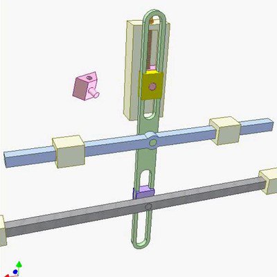 Mechanism for Increasing Stroke Length
 Screw Gear Drive